Carbon Capture Utilization and Storage (CCUS)
Discover More for "Material Selection" < - CCS Material selection - >
The primary objective of CCUS is to reduce CO₂ emissions from industrial sources and thereby mitigate climate change by safely and permanently managing the disposal of anthropogenic CO2.
CCUS - is the process of capturing carbon dioxide (CO₂) emitted by industrial activities such as natural gas production facilities, coal-fired or biomass power plants, chemical plants, and any other industries generating CO₂. The captured CO₂ is transported and either stored in underground geological formations (carbon sequestration) in the case of Carbon Capture and Storage (CCS), or utilized for industrial purposes in the case of Carbon Capture Utilization (CCU) projects.
CCU projects, such as CO₂ injection for EOR (Enhanced Oil Recovery), may be considered Carbon Neutral when assessed on a life-cycle basis. Part of the CO₂ captured can be produced back at the end of the process. The final balance results in no additional CO₂ generation.
Sequestration (Storage) Clusters
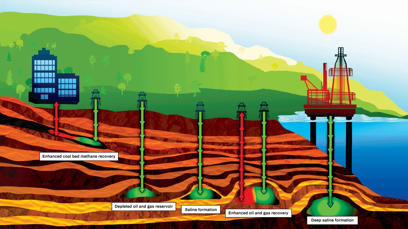 CO₂ storage locations typically are:
- Depleted Oil or Gas fields that are no longer economically viable for production. The drivers for using these are the existence of the wells and surface infrastructures in addition to the information availability concerning:
- Storage capacity
- Reservoir compartmentalization
- Injection conditions
- Cap rock sealing capability
- Saline formations that refer to any saline water bearing formation (non-potable). The saline formation must be sealed by a competent caprock to be considered for permanent storage. Contrary to usage of depleted hydrocarbon reservoir, there is no risk of CO₂ leakage through un-properly abandoned wells. The disadvantages when compared to depleted Hydrocarbon reservoirs are multiple:
- Little knowledge of the reservoir geology requiring extensive prior assessment
- Limited storage efficiency (Max 20%) often requiring prior dewatering
- Risk of either scaling or dissolution of reservoir minerals through reaction of CO2 with the aqueous medium
- Risk of overpressure resulting in cap rock failure
Additional types of underground formations for geologic carbon storage have been investigated. These are:
- Unmineable coal seams
- Basalt formations
- Organic-rich shales
Fluids To Be Injected
Captured CO₂ can contain impurities depending upon its origin (associated with natural gas versus combustion byproduct)
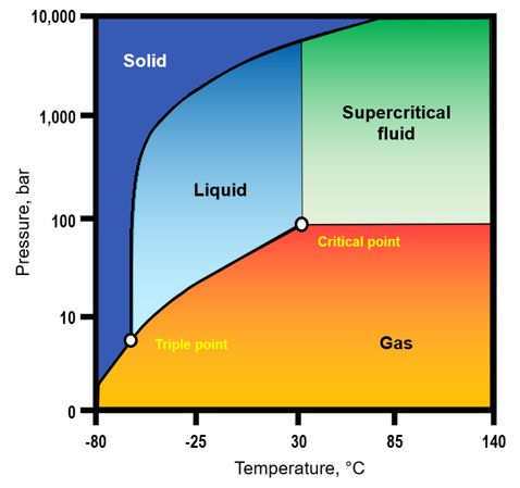
Depending upon pressure and temperature conditions at well head and along the wellbore, the injected fluid could be gas, liquid or dense phase (supercritical - highly compressible fluid that demonstrates properties of both liquid and gas).
The fluid to be injected can vary from/to:
- Clean CO₂ – Dry (negligible water content) or with some associated water.
- Contaminated CO₂ – Presence of impurities or corrosive elements, such as:
- H2S (Hydrogen Sulfide)
- O2 (Oxygen)
- NOx (Nitrogen Oxides)
- SOx (Sulphur Oxides)
Material Selection < - CCS Material selection - >
Injection Phases and Potential Risks

There is a risk of formation water flowing back into the wellbore during injection shut-in periods. In such case, formation water composition will affect the corrosion aggressiveness of the environment.
- CO₂ + Formation water (@ bottomhole) induces Potential (*) Risk of Stress Corrosion Cracking of CRA’s
- CO₂ + Condensed water (@ wellhead) induces Potential (*) Risk of Sulfide Stress Cracking
(*): Conditional to the well environment and fluids composition.
Monitoring wells
In addition to injection wells, monitoring wells play a critical role in CCS projects by ensuring the long‑term integrity and containment of the injected CO₂ plume. These wells are typically used for pressure monitoring, fluid sampling, and detection of CO₂ migration.
Similar to injection wells, monitoring wells may also be exposed to formation water backflow, particularly during pressure fluctuations or shut‑in periods. As a result, the monitoring wellbore environment may become and associated risk(s) should be assessed, even in the absence of continuous CO₂ injection. Final Material selection for this type of well will depend on Operator assessment and philosophy.
Key risks for monitoring wells include:
- CO₂‑saturated formation water inducing localized corrosion or SCC of CRA tubulars
- Ingress of formation brine containing H₂S or other aggressive species
- Long‑term exposure under low‑flow or stagnant conditions, increasing susceptibility to localized corrosion initiation
Therefore, material selection for monitoring wells should follow the same philosophy as injection wells, accounting for worst‑case fluid chemistry, temperature, pressure, and long‑term exposure conditions.
workflow (over view)
- for further information, please visit here < - CCS Material selection - >
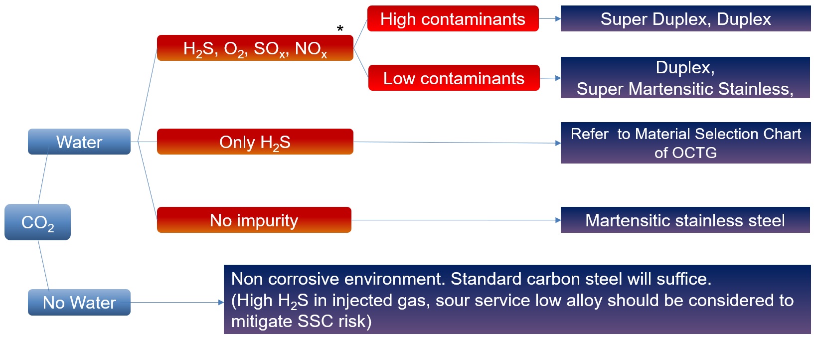
This Material Selection concept provides a quick assessment of possible materials to be used for CCUS applications, based on generic parameters such as presence of water, H2S and impurities. Once the expected environment is clearly defined (fluid characteristics composition, well conditions, etc.), a material selection will be launched using as reference existing Nippon Steel corrosion database and/or fit-for-purpose tests meant to define the most cost-effective solution for the application.
Tubular Connection Selection
Tubular Connection behavior in CCUS applications
CO2 injection wells are expected to be subjected to relatively benign mechanical loads. On the other hand, temperature variations could represent unusual challenges, specific to CCUS applications:
- Sub-zero temperature, corresponding to CO₂ injection cycles
- Rapid temperature variations transient state
- Extreme cryogenic temperature, down to -80°C, corresponding to uncontrolled decompression

Current industry standards addressing Premium connection validation (ISO 13679 and API RP 5C5) are based on hydrocarbon production conditions, in a positive temperature environment range, up to 180°C.
While not being covered by these standards, CO₂ injection in CCS application brings in additional challenges to tubular connection integrity related to sub-zero and rapid temperature variations.
VAM® Research & Development (partnership established between Vallourec & Nippon Steel Corporation since 1985) analyzed the different CCS application loading scenarios, and developed a unique methodology of validation, based on ISO 13679 / API RP 5C5, to achieve the following objectives:
- Functional validation of technological elements at low temp.(surface treatment adherence, lubricating system, …)
- Full scale sealability testing at low temperature
The outlines of VAM® CCS connection test protocol are as follows:
- Sub-zero Thermal and Pressure cycling (500 cycles)
- Thermal shock from operational temperature down to -80°C in less than 5 minutes
- Sealability under imposed temperature differential (Δtemp. = 80°C), between Pin inner and Box outer surface
- Rapid depressurization test with reduced internal pressure (100 → 0 bar)
As a result, VAM® has designed & validated with CCS leading operators, a relevant qualification testing protocol along with fit for purpose test equipment, allowing to demonstrate VAM® Premium connections mechanical & sealing integrity. Concomitantly, VAM® successfully tested its latest technology connections to this CCS protocol, demonstrating that VAM® products are fit for CCS applications usage.

- Connection test records -
| Diameter [inch] |
Weight [ppf] |
Grade [ksi] |
|---|---|---|
| 2-3/8 | 4.6 | 80 |
| 3-1/2 | 10.2 | 125 |
| 4-1/2 | 13.5 | 125 |
| 5-1/2 | 23.0 | 125 |
Prior experience in CCS projects
Nippon Steel has been involved in a number of CCS projects to support Material Selection process. Some of these are:
Large Scale CCS Project (Australia): produced CO2 from offshore gas reservoirs, is separated at the onshore gas plant and re-injected into a giant sandstone formation two kilometers beneath Barrow Island.
Offshore CCS Project (Norway): CO2 captured onshore are transported (by newly designed ships) offshore and injected/stored 2,600 meters below the seabed of the North Sea.
| Region | CO2 type | Materials | Connection |
|---|---|---|---|
| Australia | Cluster Hub (offshore) | SM25CRW-125 | VAM TOP® |
| Norway | Cluster Hub (offshore-by shipment) | SM25CRU-80, SM25CRW-125 | VAM® 21, CLEANWELL® DRY ST |
| UK | Cluster Hub (offshore-by pipeline) | SM25CRW-125 | VAM® 21, VAM TOP®-HC |
| North America | DAC* (onshore) *Direct Air Capture | SM25CRW-125 | VAM® 21 |
| North America | LNG project (onshore) | SM25CR-110, SM25CRW-125 | VAM® 21, VAM TOP® |
| Middle East | EOR/Blue ammonia (onshore) | SM2535-110 | VAM TOP® |
| Asia | EGR (offshore) | SM25CRW-125 | VAM® |
Last updated: May 2026 | K. Kanki, A. Wada, H. Ito